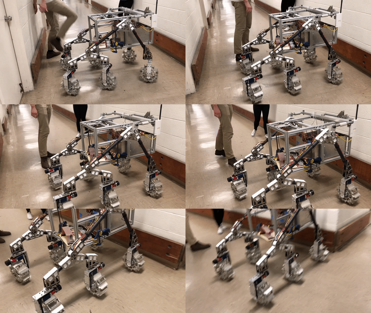
The UC Berkeley Cal Rover team is a student-run team supported by the American Institute of Aeronautics and Astronautics. The current version of the Cal Rover has six wheels, holonomic drive, and a rocker bogie type suspension inspired by NASA’s Curiosity Rover.
In 2018/2019, I worked as the Cal Rover embedded system lead. Working with the team, I helped build out the electrical/embedded systems and controls for the drive system. The drive system is composed of six brushed DC drive motors, and six servos for steering. All low-level controls are handled by a set of Cypress Semiconductors’ PSoC 5LP micro controllers. The drive motors were additionally controlled using a Basic Micros RoboClaw motor controller.
When I joined the Cal Rover team, the project was in the middle of a major overhaul. I led the team redeveloping the low-level functionality of the drive system. The low-level controls were written in C and designed to receive higher-level commands via I2C. Higher-level remote and autonomous tasks were developed in LabVIEW and Python respectively.
The drive system we developed has two modes. The first mode is a standard differential drive, in which the wheels are locked in the forward direction, to be used for longer distance treks. This mode serves the dual purpose of increasing efficiency and making best use of the rocker bogie suspension. The second mode is a swerve-style drive mode to be used at lower speeds, especially during manipulation tasks. The swerve mode uses true omnidirectional drive, as each wheel can be driven and rotated independently of the rest of the system. This allows the rover to translate (forward/backward and lateral strafe at any angle), rotate in place about its center, or strafe and rotate simultaneously.
This drive testing video was shot before the wireless communication was implemented. (original music by me)
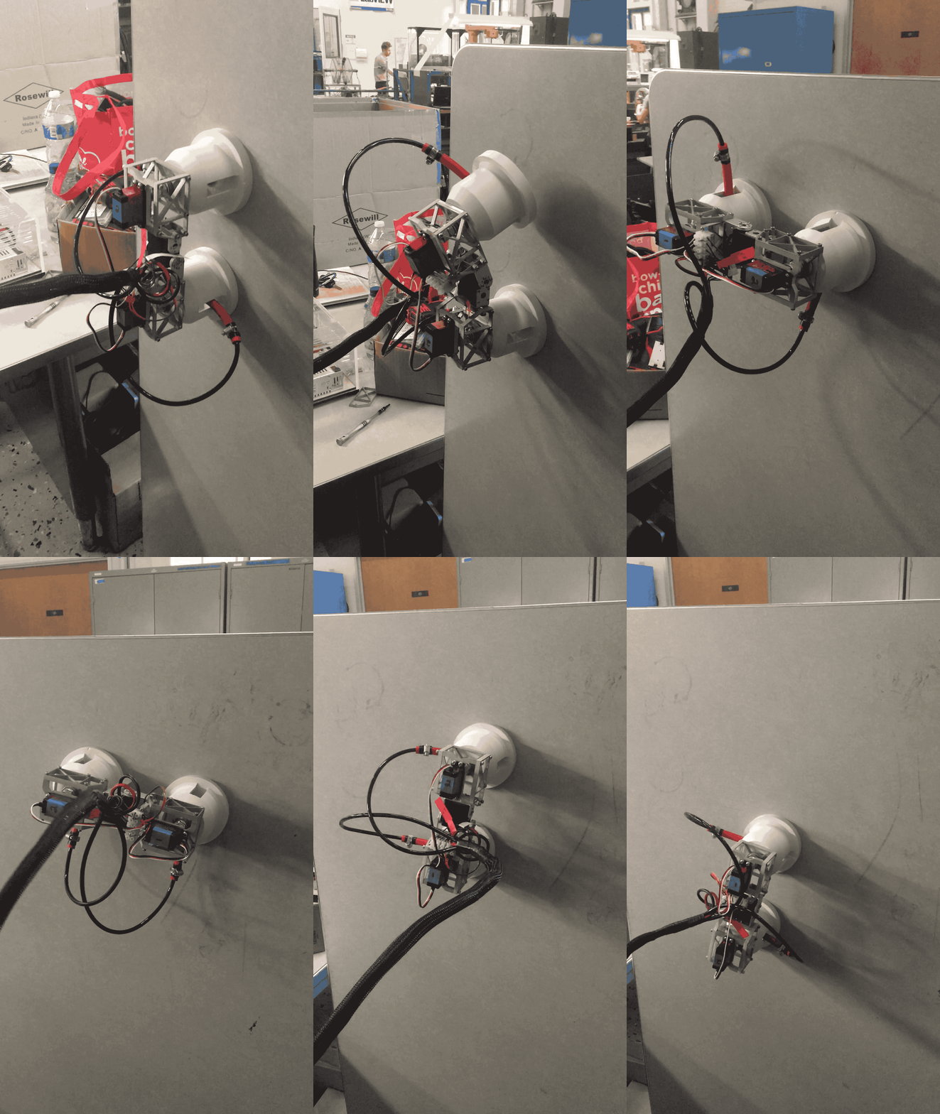
VertiCal is a suction-based climbing robot. Using three servos and two vacuum pumps as actuators, the robot moves to any location on a two-dimensional smooth surface.
I worked on the VertiCal robot as part of a five person team in a mechatronics design competition at UC Berkeley. The project won first prize in the competition, and all five members of our team were awarded the Tan Scholarship.
Our team was highly collaborative, and most design ideas were developed collectively. Working with the team, I had the opportunity to contribute to the design of the robot’s electrical and mechanical systems, as well as modeling the robot’s dynamics and sourcing parts. My main contribution was leading the development and implementation of the robot’s software/control system.
The robot’s movement is provided by three 20kg/cm servos. The suction is provided by two vacuum pumps. The negative pressure is routed to or away from the cups using relay switches and three-way solenoid valves. The main chassis of the robot was machined from 6061 aluminum, and the cups were 3D printed PLA. The robot is controlled using a National instruments MyRio-1900 micro-controller. Its software was developed in LabVIEW using state machine program architecture, and it can be remotely-controlled using a GUI on a tablet or laptop.
In the image above, the GUI is pictured top left, the robot is on the right, and the control box is below.
We originally designed the robot with all the components on-board. However, when sourcing the parts, we realized they would cost more than a group of engineering students could afford. Because of this, we decided to off-board the larger components to a control box tethered to the robot.
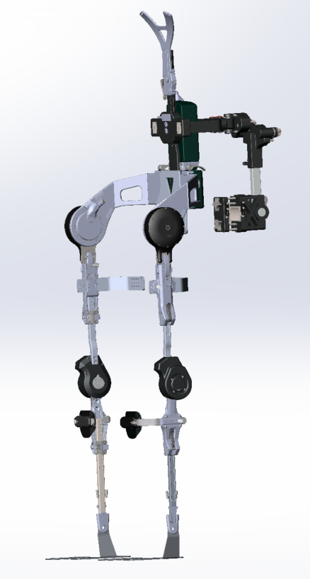
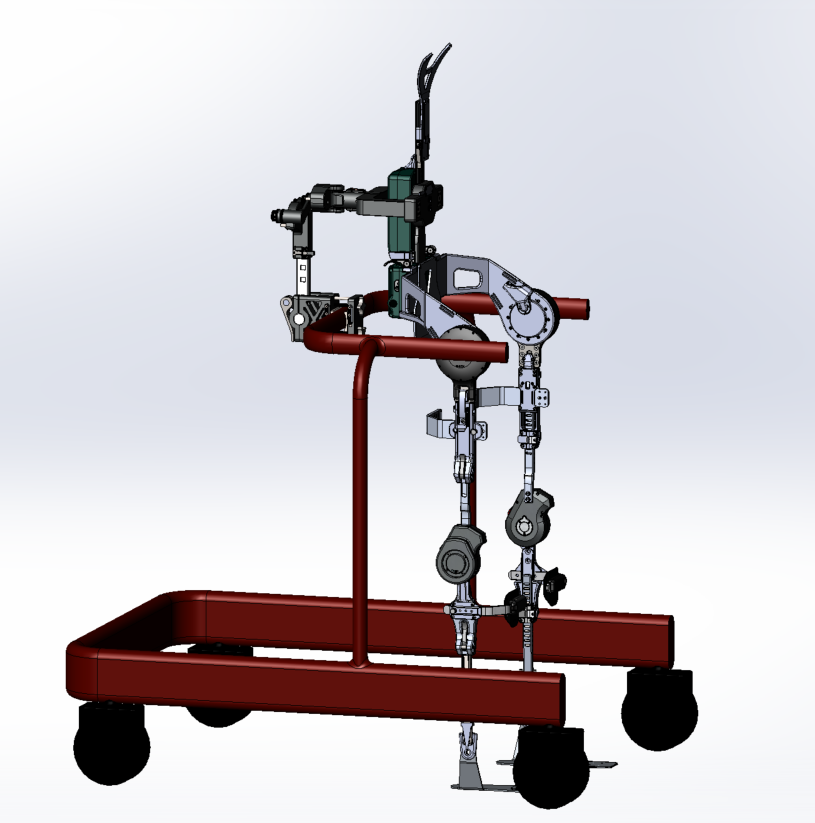
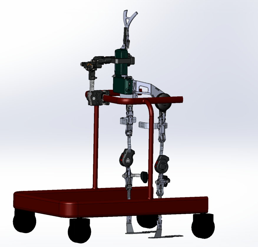
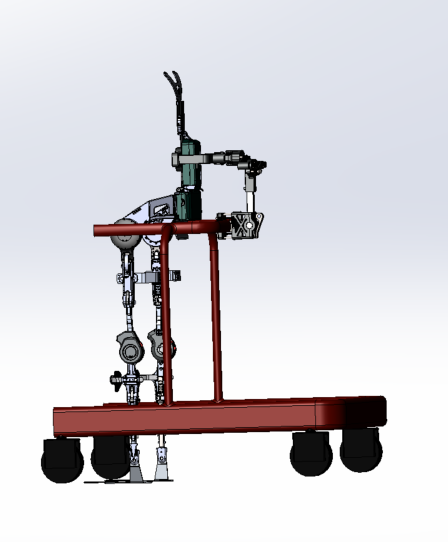
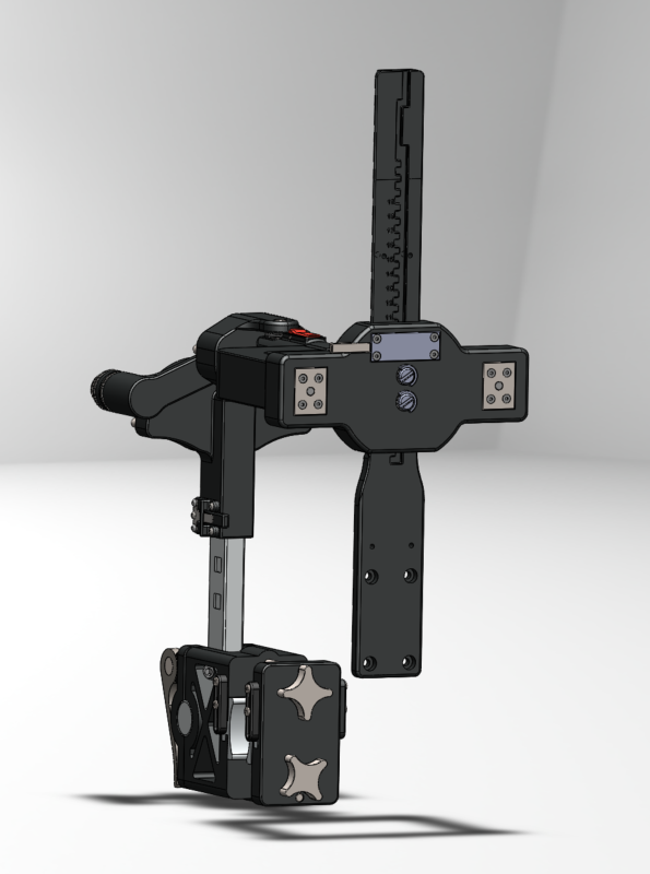
In the summer of 2018, I interned with suitX, a robotic exoskeleton company. The medical division of suitX makes wearable robotic devices designed to assist people with mobility issues. At suitX, I worked on re-designing a support arm used to attach their PHOENIX Medical Exoskeleton to a range of commercially-available medical walkers. The support arm was originally designed as part of a PhD thesis by Nicholas Errico. While medical exoskeletons can give paraplegics and others with with limited mobility the ability to walk, most of them still require some type of balance assistance—and even with crutches, some users can still be at risk of falling.
The idea behind the support arm was to give novice users of the exoskeletons the ability to practice with minimal supervision, while greatly reducing the risk of dangerous falls. This could be particularly useful for physical therapists working with more than one client at a time. In addition to fall prevention, the support arm was also designed to aid controlled locomotion by restricting movement in the sagittal plane while allowing free movement in the frontal and transverse planes.
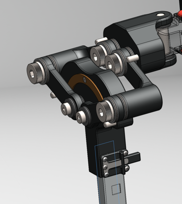
As is the case with many first versions of a product, there were a number limitations and unforeseen points of failure in the design when I received it. As part of my internship, I was asked to redesign the product. My redesign was extensive. I modeled the dynamics of a fall event to find what stresses would be placed on the support arm. I then did extensive Finite Element Analysis (FEA) to make sure components and assemblies could handle the stresses. By building out areas of high stress concentration and reducing materials in areas of low stress concentration, I was able to increase the strength of the support arm while reducing its weight. I redesigned the height and angle adjustment mechanisms and designed a quick-connect system to make the support arm easier to use. I also developed an adjustable system for attaching various other products to the spine of the exoskeleton.
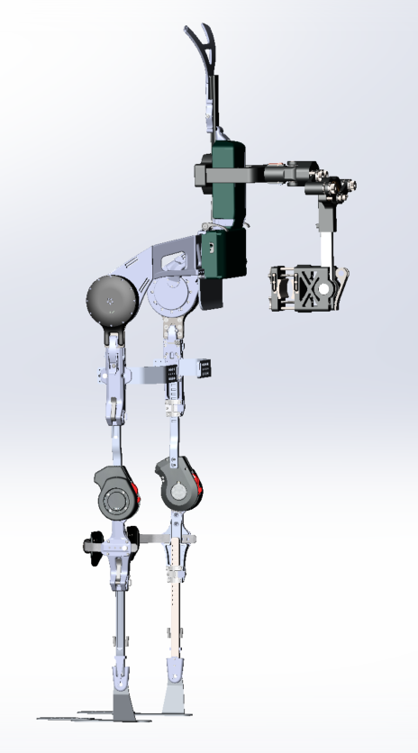
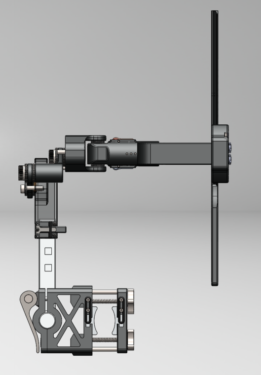
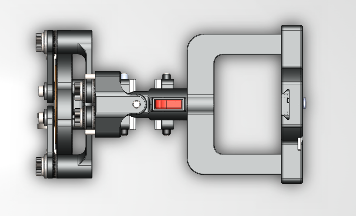
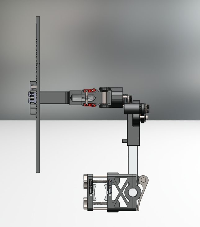
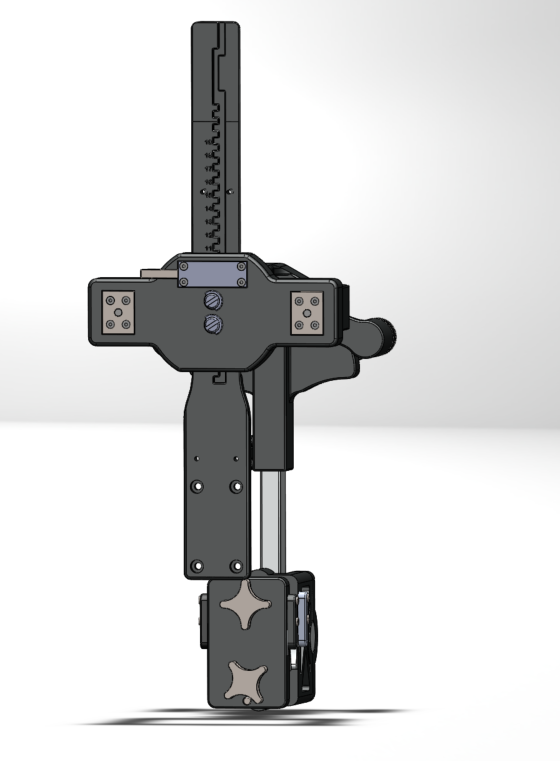
The support arm connects the cross beam of the walker to the main spinal support of the exoskeleton.
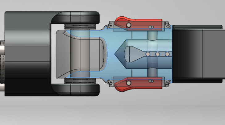
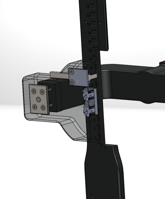
(The chassis of the quick connect mechanism is transparent in this shot.)
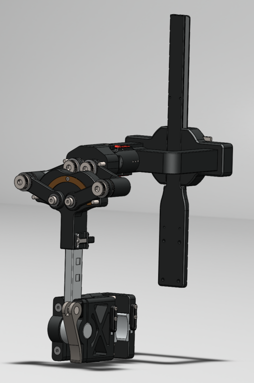
The angle adjustment mechanism (left) and cart attachment mechanism (right) are pictured here.
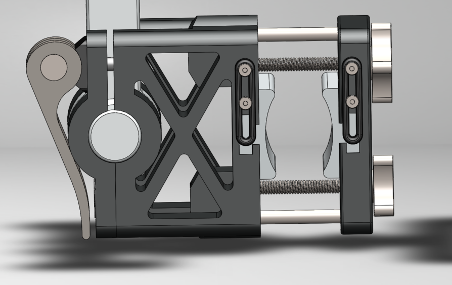
The Four Bar Mechanism allows movement in the transverse and frontal planes while constricting movement in the sagittal plane. It also has a height adjustment lever, which can be seen in the lower part of this picture.
This animation was produced as part of a final project for an Advanced Engineering Design Graphics class at UC Berkeley. Working with two other team members, we modeled a classic Kodak Pageant AV-126-TR 16mm film projector. To make our CAD model, we disassembled a Kodak Pageant, and painstakingly measured and modeled each individual component. The modeling was done with Creo Parametric (formerly known as Pro-E), and the animation was done using 3ds Max.
This project helped develop my modeling skills, and it was also great practice in managing a large CAD project working with multiple other engineers. Additionally, it served as an incredibly interesting study into a complex mechanical system, from a time when mechanical systems were king. Though the digital revolution has allowed us to make countless systems more effective and efficient, there are still many brilliant lessons to be learned from these old relics.
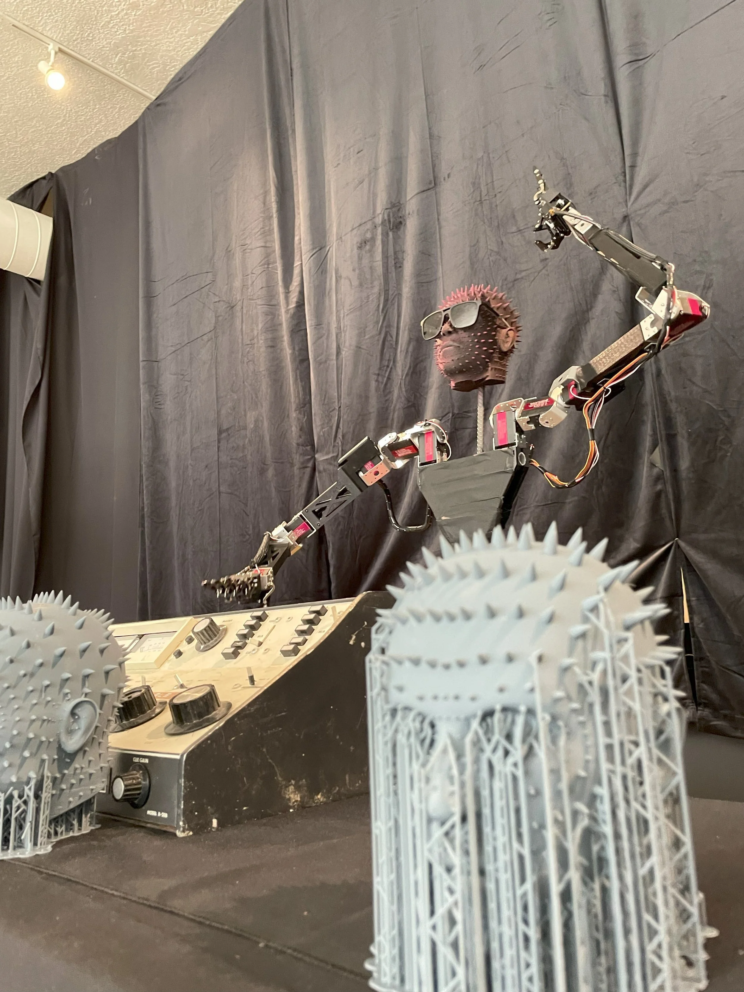
I’m an engineer and artist currently living in Albuquerque, NM. I am currently building an 8000 square foot immersive art space in downtown ABQ called Cafe Entropy. I'm obsessed with the cross section between art, science, and engineering. with the I love to create—whether it’s producing music, building immersive art experiences, programming, or making mechatronic devices, I love the process of bringing something new into the world. I am also passionate about learning. We live in such an interesting world that sometimes I find myself overwhelmed with all the things I want to learn more about. Here are a few subjects I find particularly interesting: thermodynamics, electrochemistry, energy storage, quantum mechanics, control systems, carbon capture, system dynamics modeling, ecology, embedded systems, machine learning, electrical engineering, and applied math. For me, the process of learning and creating go hand and hand. I love to dream up ambitious ideas, and then learn what I need to know to make them happen.